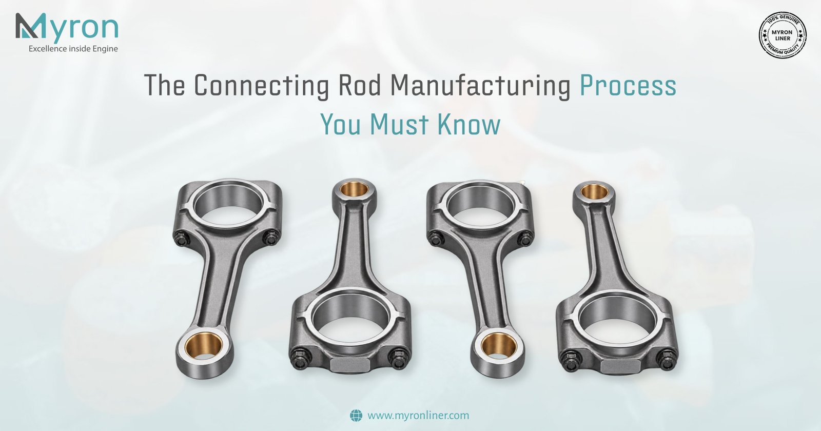
The Connecting Rod Manufacturing Process You Must Know
Introduction
In any internal combustion engine, the connecting rod is one of the unsung heroes. It connects the piston to the crankshaft.
It carries strong forces from combustion, like tension, compression, bending, and inertia. It also allows for smooth motion change. Without a reliable connecting rod, even a well-designed engine will fail prematurely.
For a company that makes engine parts, it is essential to understand the whole process of making connecting rods. This includes design, choosing materials, production methods, machining, inspection, and finishing. This guide walks you through how conrods are made.
It explains the process in simple terms. You will learn about the trade-offs involved. It also shows how to create quality aftermarket rods that last.
What a Connecting Rod Is and How It Works
Before diving into how you make one, it's helpful to recap what a connecting rod does and how it's structured.
Function and Role in an Internal Combustion Engine
- The connecting rod links the piston to the crankshaft using a wrist pin or gudgeon pin. It changes the piston's up-and-down motion into the crankshaft's rotational motion.
- As the piston moves, the connecting rod pivots at both ends (small end at the piston pin, big end at the crankpin). It transmits compressive and tensile loads from combustion and inertia.
- The rod must be strong enough to avoid bending. It should also be light to reduce moving mass. This helps with balance, efficiency, and vibration.
Read More: What Is a Crankshaft and Why Does It Matter in Engine Performance
Major Parts of a Connecting Rod
A typical connecting rod consists of:
- Small end (or "little end" ): Connects to the piston pin or gudgeon pin. This end often contains a bushing or bearing.
- Big end: Attaches to the crankpin on the crankshaft, typically via a split-cap assembly and bearing inserts.
- Shank (beam): The central body or "rod" connecting the small and big ends. Its cross-section shape (I-beam, H-beam, etc.) influences strength vs. weight.
- Bearing inserts/bushings: In the big end, you have bearing shells or inserts to reduce friction with the crank journal. In the small end, a bushing or bearing may be used.
- Bearing cap, cap bolts, and nuts: The big end is often split. This allows a removable cap to be bolted on. It makes it easier to assemble and disassemble around the crankshaft.
It is essential to understand these parts when planning the manufacturing process. Each zone needs different tolerances, surface finishes, and treatments.
Design & Material Considerations
Before you can manufacture, you must design the rod and choose appropriate materials. These decisions heavily influence cost, performance, and durability.
Strength, Weight, and Safety Margins
- A connecting rod must handle repeated loads. These include compression during combustion and tension during exhaust. It also faces bending and side forces. It must do this for thousands or millions of cycles without breaking down.
- The design aims for the highest strength-to-weight ratio. Too heavy, and you add inertial losses; too weak, and it risks failure under extreme conditions.
- Engineers choose safety factors, fillet radii, and cross-sectional shapes like I-beams and H-beams. They do this to lower stress concentration areas.
Material Options
Common materials used (especially for aftermarket, high-volume production) include:
- Forged steel alloys (e.g., 42CrMo, micro-alloyed steels) - the dominant choice for strength, durability, and cost balance.
- Aluminum alloys are lighter and often used in racing or high-revving applications. However, their strength and fatigue life can be limited under high loads.
- Powder metallurgy — sometimes used for moderate loads or cost-sensitive production, but less common in heavy-duty engine parts.
- Titanium and exotic alloys are used in high-end racing and aerospace engines. They are rare because their extreme light weight justifies the high cost.
Material selection also drives subsequent processes (heat treatment, machining allowances, surface finishing, etc.).
Tolerances & Dimensional Accuracy
In a high-volume manufacturing process, it is important to have tight tolerances. This includes bore concentricity, bearing surface finish, cap alignment, and overall rod length. Any misalignment or out-of-spec dimension could lead to premature bearing wear or catastrophic failure.
Design validation frequently includes finite element analysis (FEA) to simulate stress distribution, identify weak points, and optimize geometry before forging or machining. While we won't go into detail about FEA here, it is an essential step before making engine parts.
Methods to Create a Semi-Finished Rod
Once the design and material are chosen, the next step is to create a "blank" or semi-finished rod. This rod is then machined and finished. The two main routes are forging and billet machining.
Forging (Hot Forging / Closed-Die Forging)
This is the most common method for connecting rods in high-volume engine parts manufacturing. Many aftermarket rods also follow this route for cost, strength, and efficiency reasons.
Steps in forging a route:
- Blanking / Precut billet — raw steel billets (or rods) are cut to approximate length and weight.
- Heating — the blank is heated, often by induction heating, above its recrystallization temperature. This allows plastic deformation without strain hardening.
- Rolling / Performing — the heated blank may go through a roll forging stage. This helps to stretch or shape it into a basic form.
- Closed-die forging is when a preform is put in a pair of matched dies. The dies compress the preform, making the metal flow into the cavity. This process shapes the rough geometry of the rod, including the big end, small end, shank, and some outlines of bores.
- Trimming and flash removal involve cutting away any extra material that sticks out beyond the die edges. Holes or bore initiators may also be punched.
- Sizing, die-sinking, and intermediate forming are processes used for internal bores. Some bores, like the small end and big end, may be sized with mandrels or inserts in the die. This helps achieve dimensions that are closer to the final size.
Heat treatment — the forging may be normalized, quenched, tempered, or otherwise heat-treated to achieve desired mechanical properties.
Advantages of forging:
- Grain flow follows the shape of the rod, improving fatigue resistance.
- Efficiency in high-volume production (less material waste).
- Closer to net shape, so less machining waste.
Challenges:
- The cost is high.
- Precision is lower than that of complete machining; further machining is still needed.
- Trimming, flash removal, and handling internal features can be complex.
Billet / Machining from Solid
In this route, the connecting rod is carved entirely (or mostly) from a solid block or bar (billet). This is more common in low-volume, high-performance, or racing contexts, but is less typical for large-volume aftermarket parts due to cost.
Steps in the billet route:
- Cut a billet or bar of alloy steel to the desired size (oversize to allow machining).
- Rough machining operations (CNC milling, broaching, roughing out the shape).
- Drilling and boring small and big end holes.
- Precision finishing and balancing.
- Heat treatment (some billet rods are heat-treated before final finishing).
- Surface treatments, shot peening, crack inspection, etc.
Pros:
- Excellent dimensional control and flexibility.
- Easier to adjust for special or custom designs.
- No forging dies required.
Cons:
- Much more material waste (higher scrap).
- Slower throughput.
- It may not have the same internal grain flow advantage that forging gives.
In practice, many high-performance "billet" rods still use forging plus final machining to get the best of both worlds.
Machining and Secondary Processing
After you make the blank (forged or billet), it will go through several machining, finishing, and inspection steps. This process will turn it into a fully usable connecting rod.
Pre-machining / Stress Relief
- Annealing or normalizing may be done to relieve stresses introduced during forging and allow better machining behavior.
- If necessary, a preliminary machining pass may flatten rough surfaces, remove scale, or cut reference faces.
Bore Machining (Small and Big Ends)
- Bores must be drilled and reamed or honed to precise diameter and geometric tolerance.
- The big-end bore is often split (rod + cap) and must be aligned when assembled.
- Some processes use alignment mandrels or pin fitting to ensure perfect alignment.
Contour Machining and Profiling
- CNC milling, turning, or 5-axis milling machines create the outside shape of the rod, including the shank shape (I-beam or other).
- Features like oil holes (for lubrication), lightning pockets, balance pads, or oil passages are added.
- Chamfers, fillets, and transition radii are carefully machined to reduce stress raisers.
Cap Separation (if needed)
- If a connecting rod has the cap made as part of the forging, some processes will break the cap. This is done along a planned line, creating a "fracture-split" rod. This yields a perfectly matching cap and rod half.
- The fracture surface becomes the mating surface, often improving alignment.
- Other rods are forged or machined, already split, and the cap is machined separately.
Heat Treatment (Final)
- After machining, final heat treatments like quenching and tempering may be used. These treatments help achieve the desired material properties, such as hardness, toughness, and fatigue strength.
- This step must be managed carefully to avoid distortion.
- Some rods also receive shot peening or surface treatment to introduce compressive residual stresses that resist fatigue crack initiation.
Surface Finishing & Cleaning
- Shot peening: blasting small metal beads to impart compressive stress in surface layers, improving fatigue resistance.
- Magnafluxing (or magnetic particle inspection): a nondestructive test to detect surface and near-surface cracks.
- Grinding / polishing mating surfaces (bearing surfaces, contact areas).
- Deburring, cleaning, washing, and degreasing to remove chips or contamination.
Assembly & Balancing
- Bearings or bushings are installed in the big end or small end as required.
- Technicians bolt the rod and cap assembly together, check the torque, and confirm the alignment.
- Rods are weighed. Minor cuts or additions may balance the weight across a set. This is very important in multi-cylinder engines.
- Center-to-center length is verified.
Inspection & Quality Control
- Dimensional checks: bore diameters, roundness, alignment, tolerances, concentricity, fillet radii, surface finish.
- Material tests: hardness, metallurgical checks (microstructure, grain flow), chemical composition.
- Nondestructive inspection: Magnaflux, ultrasonic, dye penetrant.
- Fatigue testing or sample batch validation.
- Final acceptance before packaging and shipping.
Challenges, Trade-offs & Best Practices
The above describes the "ideal" flow. However, in real life, many trade-offs and challenges come up. This is especially true for aftermarket, high-volume production.
Controlling Distortion and Warpage
Heat treatment and machining stresses can distort rods. Best practices include:
- Pre-stress relief steps
- Fixturing during heat treatment
- Minimizing asymmetric removal of material
- Controlled cooling
- Final straightening checks
Tooling & Costs
- Forging dies and tooling are expensive, so amortizing cost over high volumes is critical.
- Machining tools must be durable, precise, and often custom (multi-axis CNC).
- Wear on tools for high-strength alloys is high, so tool material choice, coatings, and maintenance become essential.
Balancing Strength vs. Light Weight
- Designers often lighten interior sections (pockets or relief cuts), but need to retain enough cross-section for fatigue life.
- Fillets, transitions, and fillet radii must be generous enough to avoid stress concentration.
- Surface finishing (shot peening, polishing) helps mitigate micro-cracks and surface fatigue initiation.
Consistency & Variability
- In mass production, ensuring each rod meets spec is difficult. Slight variation in forging, heat treatment, or machining can lead to out-of-spec parts.
- Rigorous statistical quality control and sampling methods are necessary.
- Supplier control for raw material consistency (alloy, microstructure, inclusion content) is crucial.
Reference:
Connecting rod by Wikipedia[1].
FAQ
1. What material is used for making connecting rods?
Most connecting rods are made from forged steel alloys like 42CrMo or micro-alloyed steel for high strength and fatigue resistance.
2. What are the main types of connecting rods?
The common types include I-beam rods, H-beam rods, and X-beam rods—each designed for specific strength-to-weight and performance needs.
3. Why is forging preferred over casting for connecting rods?
Forging improves grain flow, increases strength, and enhances fatigue life compared to cast connecting rods.
4. What is the difference between forged and billet connecting rods?
Forged rods are shaped under pressure to create strong grain flow. Billet rods are made by CNC machining a solid steel block for high precision and customization.
5. Why is heat treatment necessary in the manufacturing process?
Heat treatment enhances mechanical strength, hardness, and fatigue resistance, ensuring the long service life of the connecting rod.
6. What causes connecting rod failure?
Common causes include fatigue cracking, poor lubrication, over-revving, or manufacturing defects like misalignment and improper heat treatment.
Reference & Trademark Disclaimer
All manufacturer names, trademarks, logos, product names, part numbers, model numbers, descriptions, and other identifying references mentioned in this article are used for identification, reference, and cross-reference purposes only.
Such references do not imply any affiliation, association, authorization, sponsorship, approval, or endorsement by the respective manufacturers or trademark owners. All trademarks, brand names, product names, part numbers, and related intellectual property remain the property of their respective owners.
MYRON LINER LLP is an independent manufacturer and supplier of engine components. The use of any third-party name or reference is solely intended to help readers identify the applicable engine, component, or application.